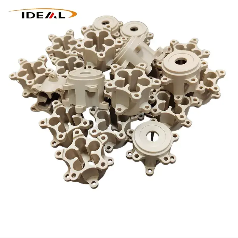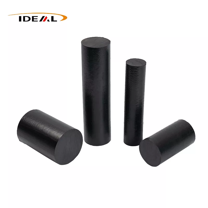
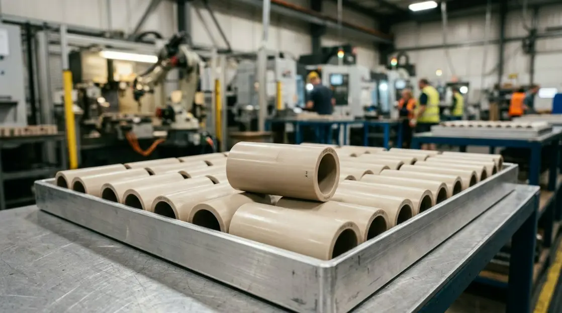
As US industries push the boundaries of mechanical and electrical design, materials like polyetheretherketone (PEEK) have evolved from premium alternatives to standard requirements. For 2026, the demand for precision-engineered PEEK Sleeves has surged across key sectors, including aerospace, defense, deep-sea exploration, and new-energy infrastructure. These long, tubular components serve as comprehensive wrappers, providing vital positioning, sealing, and insulation for critical mechanical shafts and high-voltage wiring systems.
By utilizing state-of-the-art CNC lathes, Ideal Plastic produces industry-leading China PEEK Sleeves engineered to survive environments where traditional polymers and metals fail. Whether your application requires plain PEEK or composite formulations reinforced with carbon fiber, glass fiber, or PTFE/graphite, understanding the thermodynamic and physical limitations of these protective sleeves is crucial for your design pipeline.
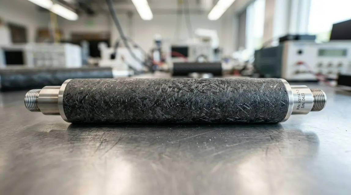
In response to demanding operational tolerances in high-stress systems, Ideal Plastic has introduced the PEEK-Armor Sync Precision Protocol. This proprietary manufacturing standard optimizes the mechanical interface between the sleeve inner diameter (ID) and the rotating or stationary shaft. By precisely controlling the molecular alignment of PEEK chains during extrusion and subsequent CNC machining, the protocol minimizes micro-vibrations, reduces the coefficient of friction, and maximizes structural stability under load.
Historically, engineering teams faced long lead times when testing customized sleeve dimensions. To close this gap, modern CAD pipelines integrate interactive 3D modeling interfaces directly with our manufacturing floor. Engineers can configure wall thicknesses, chamfers, axial oil grooves, and length intervals to receive rapid-prototyped samples that match nominal specifications within microns.
The transition to solid-state batteries and high-pressure hydrogen infrastructure requires structural components that resist chemical degradation and extreme pressure. PEEK-Armor Sleeves provide outstanding barrier protection against volatile electrolytes and prevent hydrogen embrittlement in surrounding metal components. Standard tests show zero material degradation when exposed to hydrogen gas at pressures exceeding 700 bar.
For US defense and aerospace contractors, material compliance is non-negotiable. Modern PEEK Sleeves are certified to meet UL 94 V-0 flammability ratings, guaranteeing self-extinguishing behavior and extremely low smoke and toxic gas emissions. They fully comply with MIL-spec requirements for continuous operation at 260°C (500°F), ensuring reliability in supersonic aviation and defense payloads.
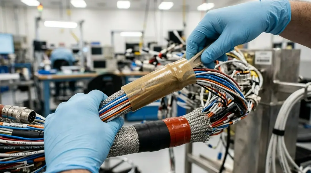
Achieving a reliable, long-term seal with PEEK Sleeves requires a structured installation methodology. Follow this 4-step engineering protocol for field and factory deployments.
Verify the exact linear length required for the shaft or wire assembly. Utilize calibrated mechanical cutters to slice the PEEK tubing at designated intervals. Clean all cut edges to eliminate micro-burrs that could compromise internal wiring or the physical seal.
Slide the wiring harness or core metallic shaft through the center of the sleeve. If applying composite carbon-filled sleeves, ensure that conductive fibers do not make direct contact with bare electrical contacts. Use specialized high-temperature dielectric films as a primary wrap where necessary.
Apply specialized elastomeric sealing rings or high-performance fluoropolymer adhesives at both ends of the sleeve. Compress the seal to the designed nominal torque. This ensures the assembly achieves an IP67/IP68 rating, protecting internal components against continuous immersion in water and high-pressure washdowns.
Place the completed assembly inside a thermal cycle chamber. Ramp temperatures up to 240°C at a rate of 10°C/minute while monitoring insulation resistance. Check for structural deformation, micro-cracking, or seal compromise to validate performance in demanding thermal zones.
While standard PEEK Sleeves serve structural and mechanical functions, advanced modifications act as conduits for optical fiber bundles and modern RGBIC lighting arrays used in commercial aircraft interiors. The table below details the performance differences across these configurations.
| Parameter | Standard Mechanical PEEK Sleeve | Optoelectronic & RGBIC Conduit Sleeve | High-Voltage Insulation Sleeve |
|---|---|---|---|
| Material Reinforcement | Plain / Carbon Fiber / Glass Fiber | Unfilled Virgin PEEK (Optical Grade) | Custom Filled / Dielectric Optimized |
| Dielectric Strength (kV/mm) | 20 - 24 | 18 - 22 | 28 - 35 |
| Max Operating Temp (°C) | 260 | 240 | 260 |
| EMI Shielding Capable | Yes (with Carbon Fiber blend) | No (Optimized for optical signals) | Excellent (High dielectric barrier) |
| Primary Target Markets | Automotive, Oil & Gas, Machined Parts | Aerospace Cabin, Smart Lighting Conduits | Power Distribution, EV Powertrains |
Engineering robust electrical insulation systems requires precise calculations of physical and electrical loads to prevent thermal runaway or dielectric breakdown over long sleeve runs.
When using PEEK Sleeves as protective conduits for high-voltage and high-current wiring, you must calculate the thermal power dissipation per unit length to ensure proper heat dissipation. Use the following formula:
P_diss = (I^2 * R_conductor * L) / (1 - (R_conductor * alpha * (T_sleeve - T_ambient)))

Where:
- P_diss = Total thermal power dissipated (Watts)
- I = Operating current (Amperes)
- R_conductor = Resistance of the inner conductor at reference temp (Ohms/meter)
- L = Total length of the PEEK Sleeve (meters)
- alpha = Temperature coefficient of resistance of the conductor (1/°C)
- T_sleeve = Target outer surface temperature of the PEEK sleeve (°C)
- T_ambient = Ambient environmental temperature (°C)
Additionally, the minimum dielectric wall thickness (t) required to prevent breakdown at a peak operating voltage (V_peak) is calculated as:
t = (V_peak * SF) / E_ds

Where:
- t = Minimum wall thickness (mm)
- V_peak = Maximum peak voltage (kV)
- SF = Safety Factor (typically 1.5 to 2.0 for aerospace applications)
- E_ds = Dielectric strength of the selected PEEK material grade (kV/mm)
Global distribution demands strict adherence to international safety frameworks. Ideal Plastic manufactures PEEK Sleeves in accordance with strict quality assurance standards:
While PEEK Sleeves are primarily industrial, they protect the high-performance sub-surface communication lines and power bus lines in premium architectural automation. By acting as high-temperature, non-flammable protective conduits, they shield physical networks (PoE and optical fiber) from damage, ensuring reliable operation for systems integrated with Matter, Apple HomeKit, and Amazon Alexa.
Using advanced Swiss-type CNC lathes, the cutting tolerances for custom lengths can be held to ±0.01 mm (0.0004 inches). Standard cutting intervals are tailored to your requirements, ensuring smooth installation without on-site trimming.
Defense installations require strict adherence to MIL-STD-810H environmental testing guidelines. Power supply calculations must include a minimum 2x safety factor for dielectric breakdown resistance and heat dissipation under high-power operations to prevent signal degradation and component failure.
As a top-tier professional manufacturer, we deliver direct factory-price solutions for dynamic scaling, engineering projects, and custom systems globally.
Visit Official Website →