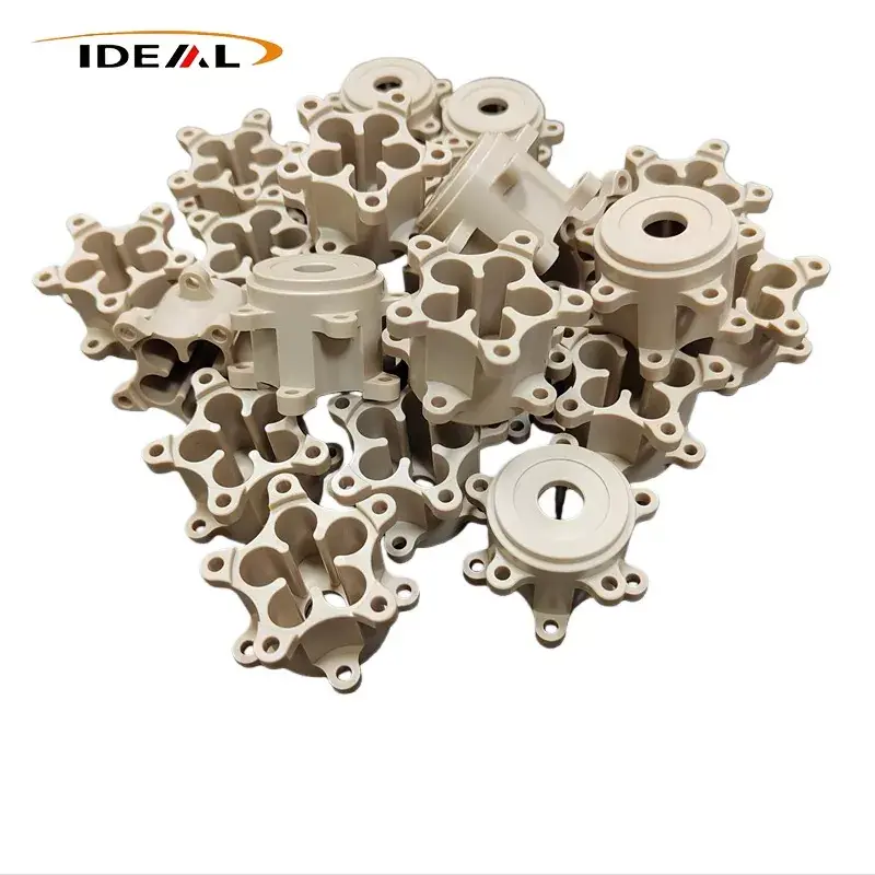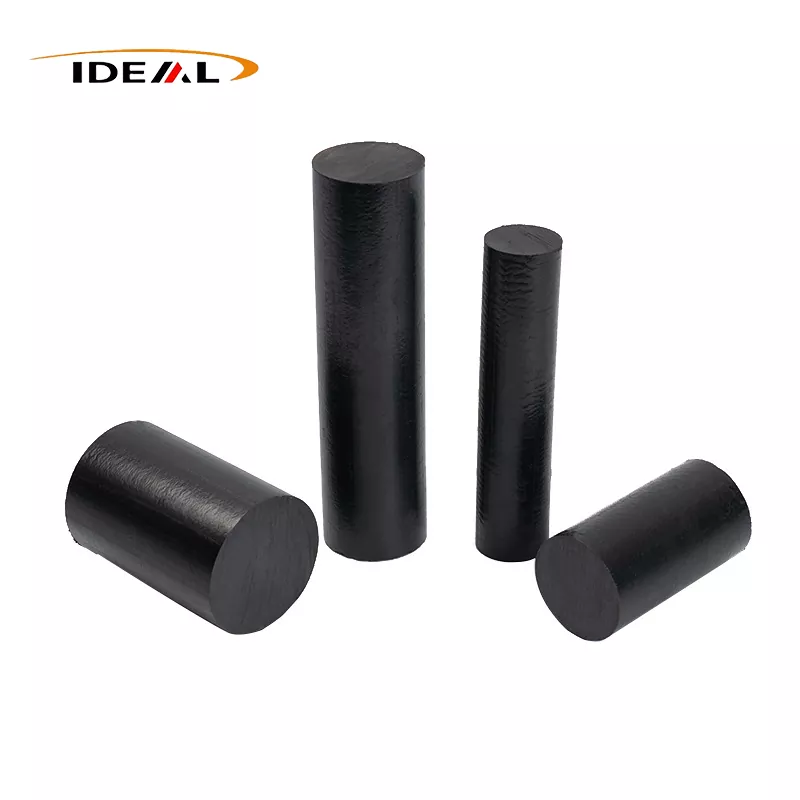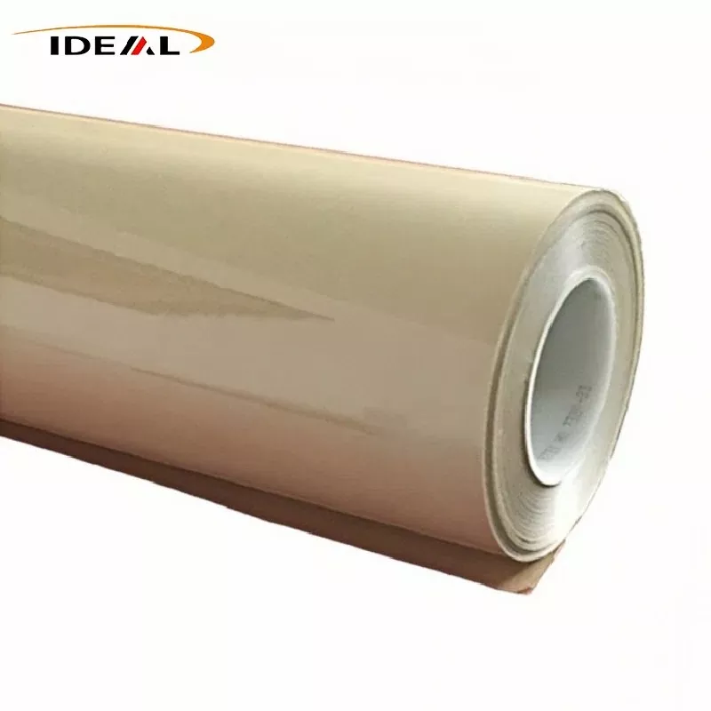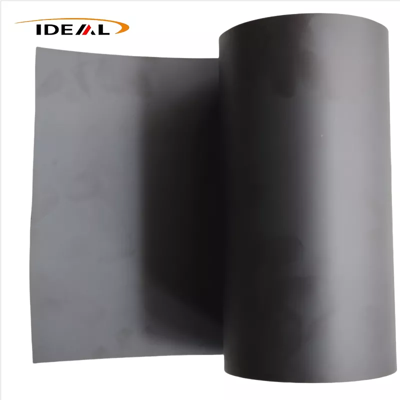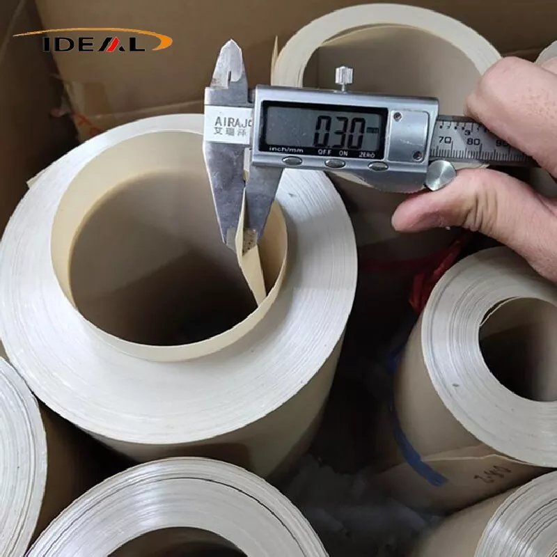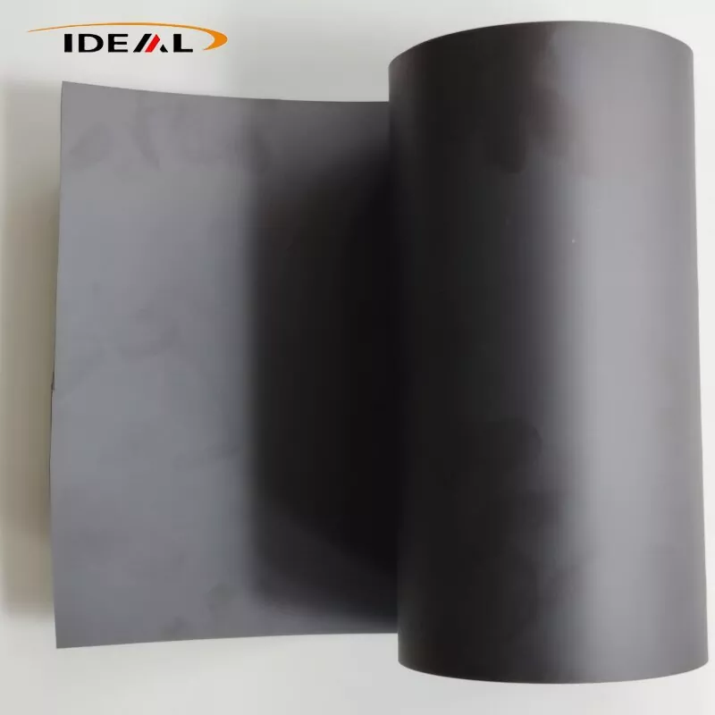
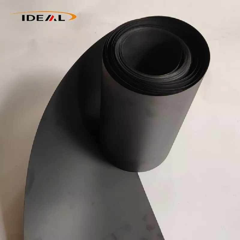
Carbon Filled PEEK Film (chopped carbon‑fiber‑filled polyetheretherketone cast film) uses semi‑crystalline high‑performance thermoplastic PEEK resin as its matrix. It is compounded with chopped PAN‑based carbon fiber and continuously formed through a T‑die flat‑die cast‑extrusion process to produce a black engineering‑plastic film material.
Carbon Filled PEEK Film retains the fundamental properties of virgin PEEK, including high‑temperature resistance, chemical resistance, hydrolysis resistance and radiation resistance. Meanwhile, it achieves substantial improvements in rigidity, thermal conductivity, self‑lubricating wear resistance and dimensional stability. The material exhibits semiconducting characteristics and basic electromagnetic‑shielding performance. It is primarily suitable for service conditions involving high‑temperature wear, heat dissipation, lightweight design, vacuum environments, aerospace, new‑energy and precision‑machinery applications.
PEEK Film with Carbon Fiber is a continuous black composite film manufactured from extrusion‑grade PEEK resin pellets blended with chopped carbon fibers, followed by casting and high‑temperature annealing. Three mainstream filler grades are available: CF10, CF20 and CF30.
CF10 low‑fill grade has the lowest melt viscosity and optimal flowability, so it is the easiest grade for cast‑film production (0.05‑0.3 mm). It features few floating fibers on the surface, maintains reasonable toughness and resists brittleness. Warpage after die‑cutting is relatively minor, delivering a good balance of reinforcement and toughness.
Shortcomings: limited rigidity enhancement, slight reduction in the coefficient of thermal expansion, moderate improvement in wear resistance, and modest gains in electrical and thermal conductivity.
CF20 shows moderate melt viscosity and can be stably cast into films (0.10‑0.40 mm). Compared with CF10, its modulus, wear resistance, thermal conductivity and dimensional stability are markedly improved. Brittleness has not reached the level of CF30, and the film still retains acceptable bending tolerance. CF20 provides the best overall balance between comprehensive material performance and cast‑film processability.
CF30 delivers the highest reinforcement, wear resistance and thermal conductivity. However, melt viscosity rises significantly, making stable production of ultra‑thin cast films difficult; reliable production is limited to thicknesses ≥0.25 mm. The film demonstrates greatly increased brittleness, and micro‑cracks may form under slight bending. The risk of warpage after die‑cutting rises substantially, and controlling surface floating fibers becomes challenging. The base CF30 pellet already has very low elongation at break. Once processed into thin‑gauge film, the release of internal residual stress significantly increases the likelihood of warpage during downstream die‑cutting operations.
The underlying principle for these property differences is that higher carbon‑fiber loading increases melt viscosity. In cast‑film processing, molten resin spreads evenly from the slit die and is drawn across a series of cooling rollers. High‑fill formulations are susceptible to cracks, surface pitting and floating fiber defects when subjected to drawing tension.
Note: This description applies only to chopped carbon‑fiber‑filled cast films; continuous carbon‑fiber prepregs are excluded, as are dedicated ESD anti‑static grades. Ordinary chopped carbon‑fiber‑filled PEEK film is not equivalent to dedicated ESD anti‑static film. Its resistivity range is unstable and it cannot be directly deployed as a semiconductor‑grade anti‑static material.
Guangzhou Ideal commenced production of Carbon Fiber Filled PEEK Film in 2014. Over the past ten‑plus years, we have upgraded production equipment, optimized manufacturing workflows, and established formal quality‑control procedures. Strict controls are implemented across every stage: incoming inspection of compounded pellets, synchronous real‑time monitoring during production, and final laboratory testing at the factory.
1. Incoming raw‑material inspection:
A. A Karl Fischer moisture tester is used to analyse raw‑material moisture content. We control the moisture content of modified pellets at ≤0.02 % to prevent bubble and pinhole defects in finished films.
B. We perform a muffle‑furnace ash‑residue test (calcination at 580‑600 °C) to measure carbon‑fiber filler loading. The permissible deviation between measured filler content and nominal specification is ≤±0.5 wt%.
C. After twin‑screw compounding for sample preparation, carbon fibers are separated via pyrolysis. Fiber lengths are counted under an optical microscope to confirm a target retained fiber‑length range of 0.2‑0.6 mm and to identify excessive fiber crushing.
2. PEEK Film with Carbon Fiber On‑line real‑time production‑line inspection:
A. On‑line thickness monitoring: β‑ray thickness gauge or laser non‑contact thickness gauge performs continuous transverse scanning across the full roll width; real‑time thickness curves are generated, and out‑of‑tolerance sections are automatically flagged. This supports closed‑loop fine adjustment of the die lip. Suitable for continuous cast‑film production ranging 0.1‑0.5 mm; thickness tolerance is held at ±0.01‑0.03 mm.
B. Online CCD visual surface‑inspection system: high‑speed industrial cameras identify surface defects including black spots, burnt particles, pinholes, longitudinal scratches and floating fibers. Defect locations are marked via ink‑jet marking; defective web segments can be removed in subsequent winding operations. Limitations: CCD inspection cannot detect subsurface embedded metallic debris or internal micro‑voids; it only examines the outer film surface.
C. Online X‑ray inspection: X‑ray online flaw detection screens the film for embedded hard metallic particles. This is high‑end optional equipment and is not a standard configuration for all production runs.
3. Off‑line finished‑product laboratory testing:
A. Dimensional and appearance inspection: film thickness is measured with a digital micrometer; width, length and roll end‑face are checked using steel measuring rules. Surface quality is assessed by visual observation combined with stereomicroscope examination to evaluate floating‑fiber severity; a distinction is drawn between faint surface texture and protruding exposed floating fibers. Surface scratches and black‑spot defects are formally recorded.
B. Microstructure detection: Specimens are prepared for metallographic cross‑section analysis. We assess carbon‑fiber dispersion, check for fiber agglomeration and quantify internal porosity. Our internal‑control target for porosity is below 2 %; we also screen for fine embedded metallic debris. DSC (Differential Scanning Calorimetry) is used to test melting‑peak temperature, crystallinity and glass‑transition temperature (Tg). Internal crystallinity is controlled within 25‑32 %; batch‑to‑batch crystallinity variation is monitored to evaluate the effectiveness of annealing treatment.
C. Mechanical‑property testing: In accordance with ISO 527‑3, tensile modulus, breaking strength and elongation at break are tested separately along the extrusion machine direction (MD) and transverse direction (TD). The MD‑to‑TD modulus ratio is calculated, with an internal control limit ≤1.6 for anisotropy management.
D. Residual internal‑stress evaluation via die‑cut warpage test: Prepare 100 mm × 100 mm square C arbon Fiber Filled PEEK Filmspecimens, lay them freely on a flat glass plate and allow them to rest at room temperature for 24 hours. The corner arch height of each specimen is measured. For standard non‑annealed grades, maximum allowable arch height is ≤6 mm; for precision offline‑annealed grades the arch height must be ≤2‑3 mm.
E. Thermal‑property testing: Heat‑deflection temperature (HDT, ISO 75) and coefficient of thermal expansion (CTE) are measured in both MD and TD directions to evaluate dimensional stability under high‑ and low‑temperature cycling.
F. Friction and wear‑resistance testing: Taber abrasion testing is conducted to determine friction coefficient and wear rate for wear‑resistance performance evaluation.
A. Metallographic cross‑section analysis and tensile testing are destructive sampling inspections; they cannot guarantee that every position on the entire roll is defect‑free.
B. Online X‑ray metallic flaw detection is premium optional equipment. Melt filtration alone cannot eliminate 100 % of the risk from trace metallic foreign contaminants.
C. The warpage test only provides indirect assessment of residual internal stress; there is no direct test method to yield a numerical residual‑stress value.
D. MD‑TD anisotropy can only be evaluated on sampled specimens; the cast‑film manufacturing process cannot fully eliminate this inherent anisotropic behaviour.
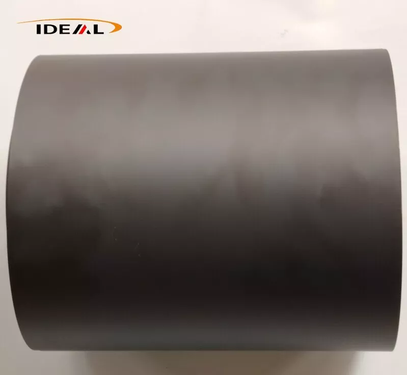
With the above‑mentioned quality‑control procedures implemented, our Carbon Filled PEEK Film features flat, smooth surfaces on both sides, with a uniform matte‑black finish and consistent colour across the web.
1. No quality‑affecting defects such as hard black spots caused by carbon agglomeration, bubbles, pinholes, through‑thickness cracks, deep scratches, oil stains or foreign inclusions.
2. Roll end‑faces are neat, without telescoping or misaligned roll layers. Winding is even and tight; a separator protective film is inserted between successive wound layers.
3. Hard raised black spots, embedded metallic hard inclusions, penetrating pinholes, continuous scratches, bubbles and wrinkles are not permitted.
4. Thickness, mechanical performance and ash‑content test results within one production batch fluctuate within acceptable ranges.
5. A COC factory inspection certificate is issued for every batch, stating batch number, filler loading, film thickness and complete mechanical test data.
| Product name | Carbon Filled PEEK Film |
| Material | CF10 PEEK, CF20 PEEK, CF30 PEEK |
| Color (filler) | Uniform matte black |
| Conventional thickness | 12μm, 25μm, 50μm, 100μm, 200μm, 500μm, 1mm |
| Width | 300mm, 500mm, 620mm, 1000mm supports any narrow width customized slitting |
| Length | 50m, 100m, long and short rolls can be customized as needed |
| sample | To be negotiated |
| Certificates | ISO9001:2012 |
| Supporting services | slitting, laminating, die-cutting processing, various types of single-piece gasket finished products can be customized |
1. Thermal conductivity: Pure PEEK has a thermal conductivity of only 0.29 W/(m·K). CF10 reaches 0.5–0.7 W/(m·K), while CF30 achieves 0.8–1.2 W/(m·K), delivering 3–4 times higher heat dissipation efficiency than pure PEEK.
2. Extremely low coefficient of thermal expansion (CTE). The carbon fiber skeleton restricts resin thermal deformation, ensuring minimal dimensional deviation during thermal cycling.
3. After annealing and shaping treatment, the film achieves a thermal shrinkage rate of ≤0.5% at 260°C, maintaining stable dimensional accuracy for ultra-thin precision gaskets.
1. The material features superior inherent self-lubrication, with a friction coefficient over 40% lower than pure PEEK. It supports long-term stable operation without oil lubrication.
2. It delivers outstanding fatigue resistance and resists cracking or fracture under reciprocating sliding and repeated compression.
3. Limitations: Carbon-filled PEEK film has lower toughness than unfilled natural PEEK film with increased brittleness, making it unsuitable for scenarios involving frequent large bending or impact stress.
4. Under long-term extreme reciprocating sliding, the film may generate trace hard fiber debris, so it is not applicable for direct contact with high-precision lithography wafer surfaces.
Internal carbon fibers form a continuous conductive network, providing stable surface resistivity ranging from 10³–10⁸ Ω/sq. The material exhibits semiconductive characteristics and basic EMI shielding performance, which absorbs and isolates stray electromagnetic interference generated by cables and power modules.
PEEK Film with Carbon Fiber integrates high thermal conductivity, excellent wear resistance, electromagnetic shielding performance and vacuum stability, supporting wide-ranging industrial applications as follows:
It serves as an EMI shielding film for airborne cables, replacing traditional copper and aluminum foil and reducing component weight by over 30%. It acts as high-temperature, oil-resistant isolation lining for aircraft engine compartments, resisting corrosion from aviation fuel and hydraulic fluid. Its radiation-resistant, low-outgassing properties make it ideal for insulating satellite vacuum modules under extreme space temperature differences. It is also used for wear-resistant sliding gaskets in precision drone transmission mechanisms.
With low outgassing, low ion precipitation, high thermal conductivity and stable vacuum-high-temperature dimensional stability, Carbon Fiber Filled PEEK Film is widely used in semiconductor processes. Typical applications include high-temperature insulating lining for etching, PVD, CVD and plasma cleaning vacuum chambers; thermally conductive wear-resistant ultra-thin gaskets for wafer transfer fixtures; heat-dissipation isolation films for CMP retaining rings; and thermally conductive wear-resistant lining for high-temperature chip test benches.
It is applied to self-lubricating sliding lining films for high-speed linear guides and conveyor rollers, high-temperature release films for injection and hot-press molds, heat and oil-resistant sealing sheets for hydraulic valves and pump bodies, and anti-friction thermal isolation pads for robot joints to avoid frictional heat accumulation.
Suitable for thermal insulation lining of electron microscope and optical coating machine vacuum chambers, high-temperature corrosion-resistant fixture gaskets for physical and chemical testing equipment, and radiation-proof protective films for nuclear detection instruments.
1. Ultra-high-purity semiconductor processes involving direct wafer contact, where carbon debris shedding may cause surface contamination.
2. Applications requiring stable ESD performance within 10⁶–10⁹ Ω/sq, as this material exhibits uncontrolled, wide resistivity fluctuation and cannot meet standard static-dissipative requirements.
3. Components requiring repeated bending and flexible resilience, due to the material’s inherent brittleness and low elongation at break.
4. Optical transparent components, as the film is fully black and opaque.
5. Ultra-high-flatness zero-warpage sheet applications. The casting process creates inherent fiber orientation; annealing only relieves residual stress and cannot achieve complete zero warpage. Ultra-high flatness requires additional CNC double-sided precision milling.
6. Working conditions with strong oxidizing media such as concentrated sulfuric acid, which will corrode the PEEK substrate.
A1: For the mainstream thickness range of 0.1–0.5 mm, general industrial grade delivers a thickness tolerance of ±0.02–0.04 mm, while precision grade achieves ±0.01–0.03 mm. Roll width tolerance is ±2 mm, and cut sheet tolerance is ±1 mm. Ultra-thin gauges below 0.1 mm adopt relaxed tolerance standards, which are confirmed by technical agreement.
A2: Post-die-cutting warpage is mainly caused by locked-in residual internal stress generated during extrusion casting, as well as anisotropic shrinkage induced by machine-direction carbon fiber orientation. Offline-annealed grades effectively reduce warpage risks, though inherent material anisotropy cannot be fully eliminated. Customers with ultra-precision processing demands can implement on-site secondary annealing to further stabilize flatness.
A3: To minimize residual stress and anisotropy of cast carbon-filled PEEK film, we adopt core process controls including gradient slow cooling in place of rapid quenching, low drawing tension, low-shear optimized screw configuration, and professional offline annealing treatment. Our QC system strictly monitors the MD-TD modulus ratio and die-cut warpage level. Note that inherent material anisotropy can only be mitigated, not completely eliminated.
A4: Master roll widths range from 300–650 mm and can be further slit into custom narrow widths. Roll length varies by thickness: thin films of 0.1–0.25 mm are typically 25–50 m per roll, and medium-thickness films of 0.3–0.5 mm are 50–100 m per roll, all equipped with a 76 mm inner diameter core.
A5: Standard carbon-filled PEEK film features unstable wide-range semiconductive resistivity of 10³–10⁵ Ω/sq. It is not a formal ESD-controlled static-dissipative material and cannot maintain stable resistivity within the standard 10⁶–10⁹ Ω/sq ESD range. Specialized ESD-stabilized PEEK film is required for formal semiconductor ESD applications.
A6: No. Standard carbon-filled PEEK film sheds fine carbon micro-particles under frictional sliding, causing serious contamination when in direct contact with wafers. This material is only suitable for non-wafer-contact wear liners and isolation shims inside semiconductor equipment. Wafer-contact precision components must be fabricated from high-purity semiconductor-grade ESD PEEK materials.