Engineers specifying reinforced polyetheretherketone (PEEK) tubing face an immediate decision: what type of fiber reinforcement will keep the part alive in the field. Unfilled PEEK handles high heat and harsh chemicals effortlessly. But under high continuous loads or extreme temperatures, the raw plastic creeps. You add fibers to stop that dimensional shift. The choice almost always narrows down to 30% carbon fiber (CF30) or 30% glass fiber (GF30). Choosing wrong means premature wear on mating parts, unexpected electrical shorts, or catastrophic thermal degradation.
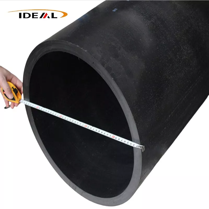
You specify carbon fiber reinforced PEEK pipe when the application involves moving parts, sliding friction, or a strict requirement for static dissipation. Carbon fibers act as a microscopic dry lubricant. They also pull heat away from the contact surface, preventing localized melting or deformation under heavy loads.
Specify PEEK GF30 when you need maximum electrical and thermal insulation in a purely static, structural application. Glass is highly abrasive. If you use a GF30 tube as a bearing or bushing against a steel shaft, the glass fibers will chew up the mating metal rapidly. CF30 spares the metal shaft while maintaining the structural rigidity of the plastic part.
The reason unfilled PEEK works so well comes down to its specific molecular structure. It features alternating aromatic rings and ether bonds. The ether bonds provide molecular flexibility, giving the plastic its inherent toughness and impact resistance. The aromatic rings provide extreme stiffness and thermal stability. That setup gives it great heat resistance, plus a precise balance of toughness and stiffness. Under heat or pressure, PEEK doesn’t warp easily, and it holds up well against repeated stress.
PEEK also relies on a highly semi-crystalline structure. It maintains a crystallinity level around 25% to 35%, which helps it keep its mechanical properties intact even as temperatures climb toward its melting point. Precise thermal management during extrusion ensures the polymer chains fold into these highly ordered crystalline structures. If a manufacturer cools the extruded tube too quickly, the plastic remains amorphous, turning translucent and losing its chemical resistance and high-temperature strength.
When you compound this matrix with chopped carbon or glass fibers, you interrupt the neat folding of polymer chains, but you gain a rigid internal scaffold. The polymer matrix transfers applied stress directly to the much stronger, stiffer fibers. This restricts the movement of polymer chains, halting creep and dramatically increasing tensile strength. It also drops the Coefficient of Linear Thermal Expansion (CLTE) to levels closely matching aluminum or steel, allowing engineers to design tight-tolerance metal-to-plastic press fits that will not loosen when the assembly heats up.
Adding carbon fiber is not a linear upgrade. There is a steep penalty in manufacturability. As fiber content increases, the melt viscosity of the plastic spikes. In an extruded tube, these fibers tend to align in the direction of the flow, meaning the tube develops incredible tensile strength along its length, with slightly lower strength along its hoop axis.
A 10% carbon fill provides a modest bump in stiffness while keeping the melt flow index high enough for complex, thin-walled extrusions. It remains relatively easy to machine and resists brittle fracturing.
Stepping up to 30% carbon fiber represents the industry standard. It balances massive tensile strength gains with acceptable machinability. This ratio provides the structural integrity needed for high-pressure applications without entirely sacrificing the plastic's natural toughness.
At 40% carbon fill, you achieve maximum rigidity. The trade-off is extreme viscosity during manufacturing. Extruding or injection molding 40% CF tubes requires precise temperature control to prevent voids. The resulting material is highly brittle. Machining 40% CF PEEK requires polycrystalline diamond (PCD) tooling, as standard carbide end mills will lose their cutting edge in minutes when cutting through that volume of abrasive carbon.
Unfilled PEEK has a Heat Distortion Temperature (HDT) around 152°C. Add 30% carbon or glass fiber, and that HDT jumps to 315°C. Both filled materials handle extreme ambient heat with ease.
The divergence lies in electrical pathways. PEEK is naturally a highly effective insulator. Adding glass fiber keeps it that way, maintaining high volume resistivity. Adding carbon fiber drops its volume resistivity drastically. CF30 is inherently anti-static. By adjusting the carbon matrix, manufacturers can produce an anti-static PEEK cylinder or fully conductive PEEK tubing. If your fuel line or aerospace component needs to ground static charge safely, carbon fiber is mandatory. Glass fiber will trap that charge until it builds enough voltage to arc, potentially causing a catastrophic failure in volatile environments.
Tribology—the study of friction and wear—is where CF30 and GF30 separate entirely based on their physical interaction with mating surfaces.
| Material Variant | Dynamic Friction Coefficient (vs Steel) | Mating Surface Wear Profile | Thermal Conductivity |
|---|---|---|---|
| Unfilled PEEK | 0.30 - 0.40 | Low (Non-abrasive) | Low (Insulator) |
| PEEK CF30 | 0.15 - 0.20 | Very Low (Self-lubricating) | High (Dissipates heat) |
| PEEK GF30 | 0.40 - 0.55 | High (Highly abrasive) | Low (Insulator) |
In dynamic loads, heat buildup destroys plastics. Every polymer has a Pressure-Velocity (PV) limit. If pushed past this limit, the plastic cannot shed frictional heat fast enough, leading to rapid melting and component failure. CF30 excels in bearings, seals, and wear rings because carbon fibers act as thermal conduits, pulling heat from the friction interface and dispersing it through the tube body.
Carbon fibers also act as a solid lubricant. As the PEEK wears microscopically, it leaves a thin tribological film of carbon on the mating surface, lowering the friction coefficient further over time.
Glass fibers do the exact opposite. They are thermal insulators, meaning frictional heat stays trapped at the contact point, lowering the effective PV limit of the part. Worse, exposed microscopic glass fibers act like sandpaper. Under dynamic load, a GF30 tube will aggressively score and wear down the metal shaft it rides against. Use glass for static structural standoffs. Use carbon for anything that moves.
Engineers specify these tubes based on environmental extremes that destroy standard engineering plastics like Delrin or Nylon.
In aerospace applications, weight reduction drives material choice. A machined carbon fiber tube replaces aluminum and titanium in fuel systems, drone airframes, and structural standoffs. It sheds significant weight while resisting aggressive aviation fluids, hydraulic oils, and jet fuel.
In the medical field, a PEEK tube for medical instruments must survive hundreds of cycles in a high-temperature steam autoclave without degrading, warping, or losing dimensional stability. Carbon-filled variants provide the high stiffness required for surgical targeting guides, endoscopic handles, and external fixation components.
Energy and offshore drilling operations rely on extruded carbon filled PEEK for downhole wireline logging tools and sensor housings. The material survives continuous exposure to sour gas (H2S), extreme hydrostatic pressure, and ambient temperatures exceeding 200°C deep underground.
Extruding filled PEEK is notoriously difficult. Fibers can clump during the melt phase, creating dry spots, resin-rich zones, or voids hidden inside the tube wall. A 1mm void in a PEEK tube wall acts as a severe stress concentrator. Under cyclical loading or high hydrostatic pressure, micro-cracks propagate from this void until the part shears completely. Because carbon-filled PEEK is pitch black and completely opaque, you cannot visually inspect the interior for these flaws.
To guarantee structural integrity, top-tier production relies on AI-Driven Defect Detection. This process pairs ultrasonic acoustic scanning or advanced X-ray imaging with machine learning algorithms. It identifies micro-voids, fiber agglomeration, and concentricity variations in real-time as the tube leaves the extrusion die. The system maps acoustic reflections to physical defect sizes instantly, rejecting compromised sections of tubing before they are shipped. Catching these internal defects guarantees the final machined tube wall will not fail under pressure in the field.
Specifying the right polymer blend is useless if the final geometry requires too much post-processing. PEEK is an expensive raw material. Buying a solid rod and machining 80% of it away into chips destroys your project budget and wastes valuable CNC machine time. Sourcing near-net-shape tubes drastically cuts production costs and material waste.
As a dedicated factory, Guangzhou Ideal Plastic operates specialized extrusion, injection molding, and CNC machining lines specifically for high-temperature engineering plastics. They produce Carbon fiber Filled PEEK tubes with carbon fill rates ranging from 10% to 40%. The facility extrudes massive profiles, handling custom dimensions ranging from 15mm up to 458mm across inner and outer diameter specifications.
All materials are backed by ISO9001 quality management, alongside REACH and RoHS certifications. This ensures full compliance for global aerospace, medical, and precision manufacturing supply chains. By matching the correct carbon fill rate to a near-net-shape extrusion, you get the exact mechanical properties you designed for, delivered in a geometry that minimizes your machining overhead.