



The short answer: choose carbon-fiber-filled PEEK tube when added stiffness and dimensional stability justify its trade-offs
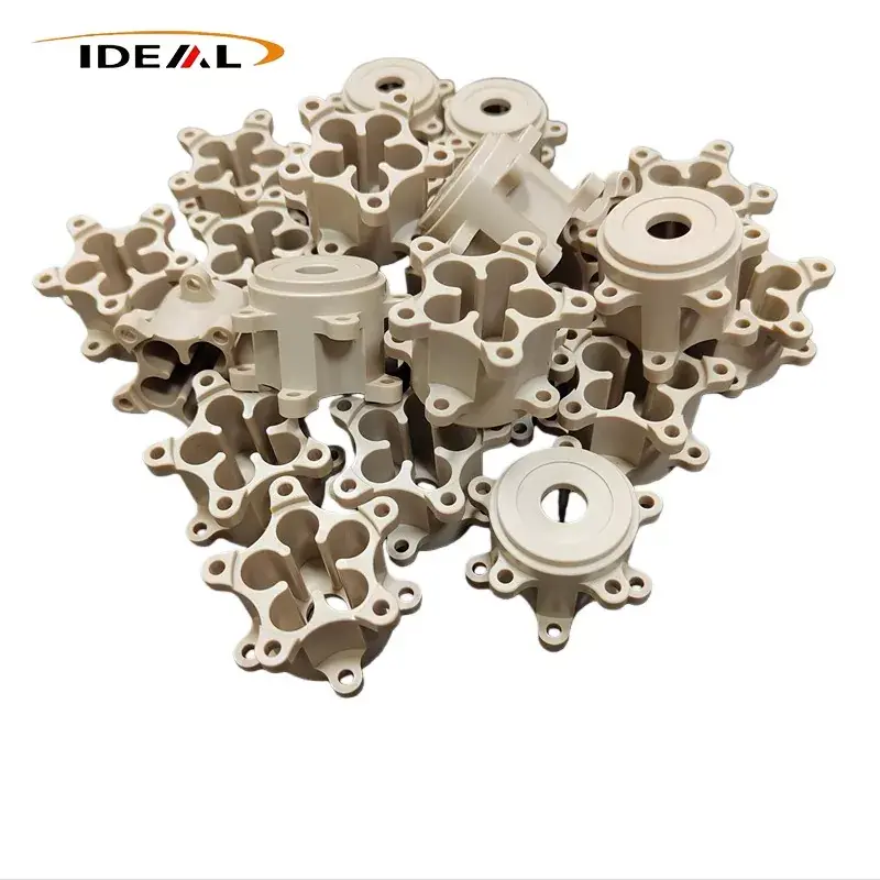
PEEK pipes are hollow semi-finished shapes used as supplied or machined into parts such as bushings, sleeves, seals, valve components and insulating bodies. Carbon fiber is added when unfilled PEEK does not provide enough stiffness, dimensional control or resistance to deformation under mechanical and thermal load.
That does not make carbon-filled material the automatic premium choice. It can be less forgiving than virgin PEEK, harder on cutting tools and electrically different. The right decision depends on load direction, temperature, chemical exposure, mating surfaces, electrical requirements and the amount of stock you expect to remove. GuangZhou Ideal offers Carbon Fiber Filled PEEK Pipes with adjustable carbon-fiber content from 10% to 40%; the company identifies 30% as the commonly used ratio.
Pipe, tube and tubing may describe the same semi-finished stock—but dimensions must be stated unambiguously
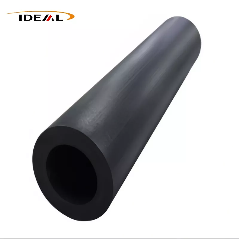
In polymer stock catalogs, “PEEK pipe,” “PEEK tube” and “PEEK tubing” are often used interchangeably. Buyers should not assume that these terms follow metal-piping conventions. A supplier may be describing a thick-wall machining blank rather than a pressure-rated line intended to carry fluid as installed.
The purchase drawing, not the noun, should control the order. If pressure service is involved, semi-finished stock dimensions alone do not establish pressure capability. The finished geometry, joints, temperature, media, load history and applicable design standard all need separate engineering review.
Define OD, ID, wall thickness, length and machining allowance on a dimensioned drawing
State the outside diameter, inside diameter and length, then identify whether each value is nominal, as-produced or required after machining. Include concentricity, straightness, roundness, surface finish and end condition where they affect the finished part. A general plus-or-minus diameter tolerance does not control bore-to-OD concentricity.
Leave enough machining allowance to clean up the skin and correct expected distortion, but not so much that material cost and machining time climb unnecessarily. Thin finished walls need special attention: chuck pressure, cutting heat and residual stress can move a bore after it leaves the machine.
Treat published size ranges and ±0.02 mm tolerance as claims to clarify, not guarantees for every ID/OD combination
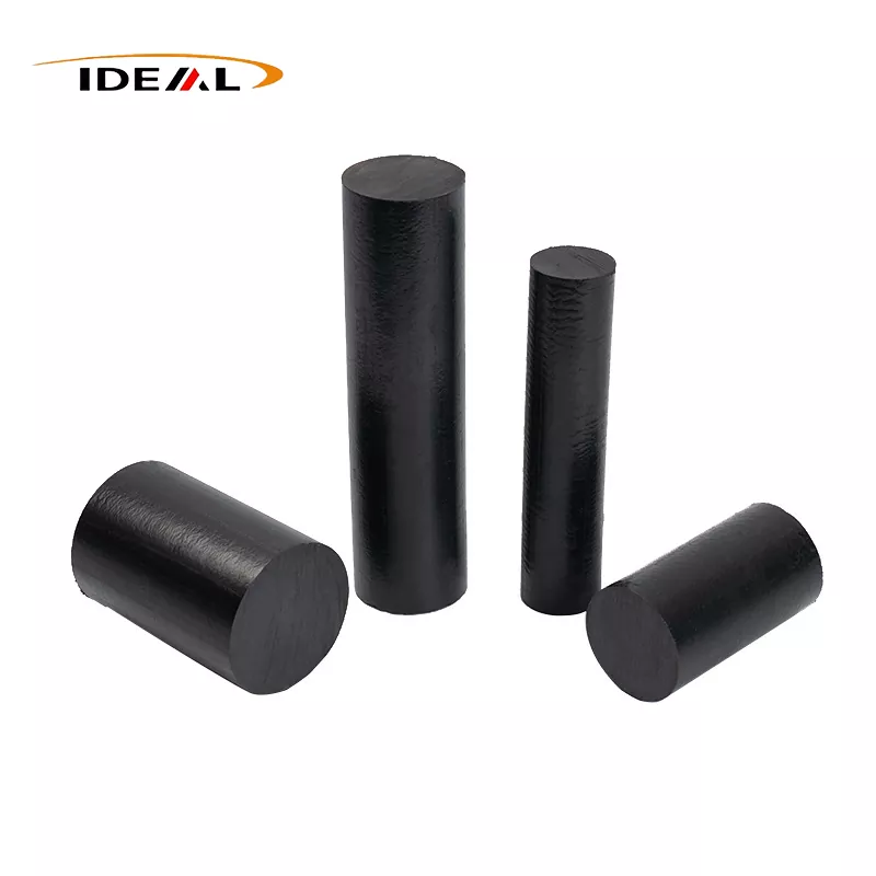
GuangZhou Ideal’s product page lists black material, nominal ID of Φ20–458 mm, OD of Φ15–404 mm, lengths of 1,000 mm and 3,000 mm, and a stated tolerance of ±0.02 mm. Those ranges should not be read as a matrix of freely interchangeable dimensions; a valid tube must have an OD larger than its ID.
Before placing an order, ask which ID/OD combinations are available and what feature the tolerance covers. Also confirm the measurement temperature, inspection method, sampling plan, straightness criteria and whether the tolerance applies to stock or a machined surface. The published PEEK tube sizes and tolerance information are a useful RFQ starting point, not a substitute for an accepted drawing.
What carbon fiber changes in PEEK—and what it does not automatically improve
Carbon fibers restrict movement within the PEEK matrix. In a suitable grade and orientation, that generally raises stiffness, reduces dimensional change under load and improves stability as temperature changes. These effects can help a machined sleeve hold geometry or reduce creep where virgin PEEK would move too much.
The reinforcement also introduces directionality. Manufacturing route and material flow can align fibers, so axial and through-wall properties may differ. Carbon fiber does not automatically improve every wear interface, preserve electrical insulation or increase resistance to every chemical. It can also reduce ductility and make edges more prone to chipping during aggressive machining or assembly.
Compare virgin, carbon-fiber-filled and other modified PEEK grades on stiffness, wear, electrical behavior, chemical exposure and machinability
| Decision factor | Virgin PEEK | Carbon-fiber-filled PEEK | Other modified PEEK grades |
|---|---|---|---|
| Stiffness and dimensional stability | Useful where toughness and unfilled material behavior are priorities | Usually favored when deflection, creep or thermal movement controls the design | Glass-filled or other reinforced grades may offer a different balance of stiffness and electrical behavior |
| Wear | Performance depends heavily on load, speed, temperature and counterface | May improve some wear conditions, but exposed fibers can affect the mating surface | Bearing grades may be preferable where friction and wear are the primary requirements |
| Electrical behavior | Normally selected where insulation is required | May have lower resistivity, but the carbon percentage alone does not define an electrical class | Formulations can be tailored for insulation, static control or conductivity; verify actual data |
| Machining | Generally less abrasive to tools | Carbon fiber increases tool wear and can contribute to edge breakout | Tool response depends on the filler package |
For machining carbon-fiber-filled PEEK tube, use sharp, suitable tooling and controlled workholding. Watch bore finish, heat generation and fiber breakout rather than relying only on an outside-diameter reading. If chemical exposure is critical, assess the complete grade against the actual fluid, concentration, temperature, pressure and exposure time.
A “30% carbon fiber PEEK tube” label is not a complete material specification
The percentage tells you filler loading, but not enough to approve a material. You still need the resin and compound grade, manufacturing route, fiber form, quality controls and property data for the supplied stock. Clarify whether the stated percentage is defined by weight or another basis.
Also ask whether the tube will come from one production lot and whether the supplier can provide lot-linked inspection records. A prototype that machines cleanly does not prove that later stock will behave identically if the compound, process or fiber orientation changes. Approve the exact grade and stock form, not a generic “30% CF PEEK” description.
Supplier data must be matched to the actual grade, test method, fiber orientation and service conditions
Datasheet values are useful only when they represent the material you will receive. Check specimen orientation, conditioning, test temperature and test method. Injection-molded coupon data may not predict the behavior of a thick-wall tube machined across a different fiber direction.
For high-temperature applications, compare properties at the service temperature rather than using room-temperature values. For chemical service, account for simultaneous stress and heat. If tight dimensions matter, request measurements on the supplied geometry and agree on how parts will be conditioned before inspection.
Validate volume and surface resistivity before treating carbon-fiber-filled PEEK as conductive or static-dissipative
Carbon fiber can lower PEEK’s electrical resistivity, but conductivity does not follow directly from filler percentage. Fiber distribution, contact between fibers, orientation, wall thickness and processing all influence the result. A material described as carbon reinforced may still miss your required resistance range.
Put the required volume resistivity or surface resistivity range on the drawing or material specification, along with the test method and conditioning requirements. If charge dissipation is safety-critical, test representative tube stock or finished components. Do not substitute a carbon-content certificate for electrical measurements.
RFQ checklist: confirm carbon-fiber content, geometry, tolerances, surface finish, inspection records, compliance documents, quantity, lead time and landed delivery
- Material: exact PEEK grade, carbon-fiber percentage and how that percentage is defined.
- Geometry: OD, ID, wall condition, length, end condition and machining allowance.
- Controls: dimensional tolerances, concentricity, straightness, roundness and surface-finish requirements.
- Performance: service temperature, loads, chemicals, wear interface and required electrical behavior.
- Evidence: applicable test data, lot traceability, inspection report and required compliance documents.
- Commercial terms: prototype and production quantities, lead time, packaging, Incoterms and landed delivery to the U.S. destination.
- Acceptance: approved drawing revision, inspection method and procedure for handling nonconforming stock.