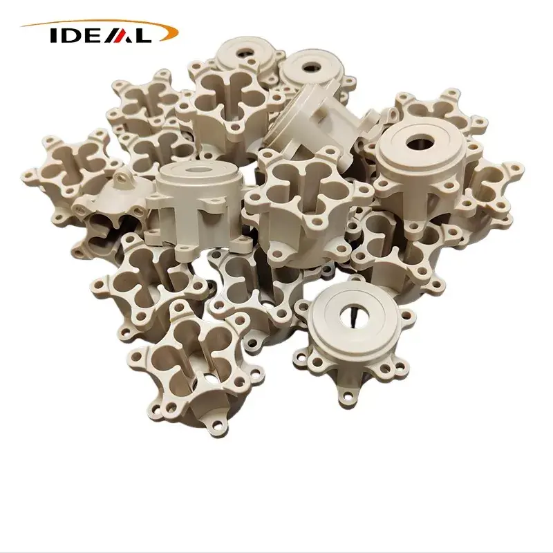
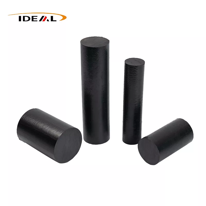
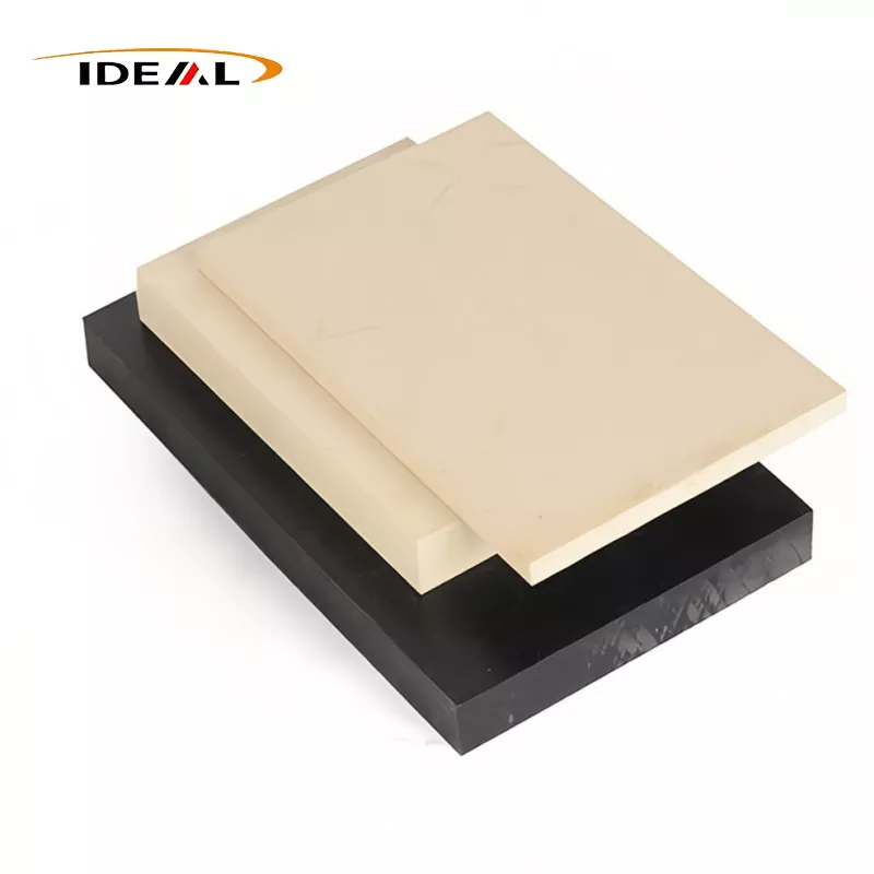
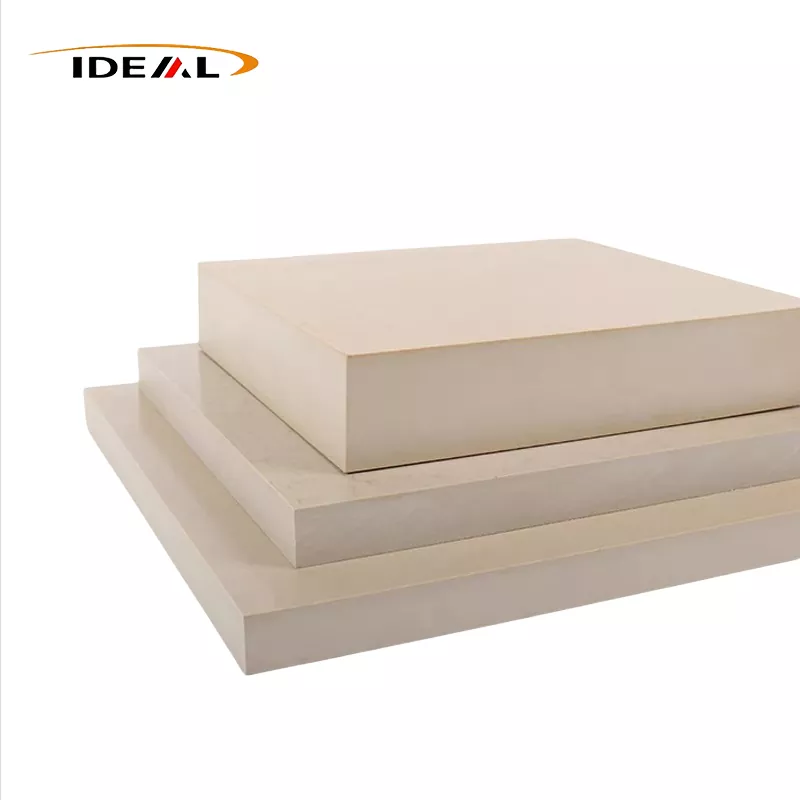
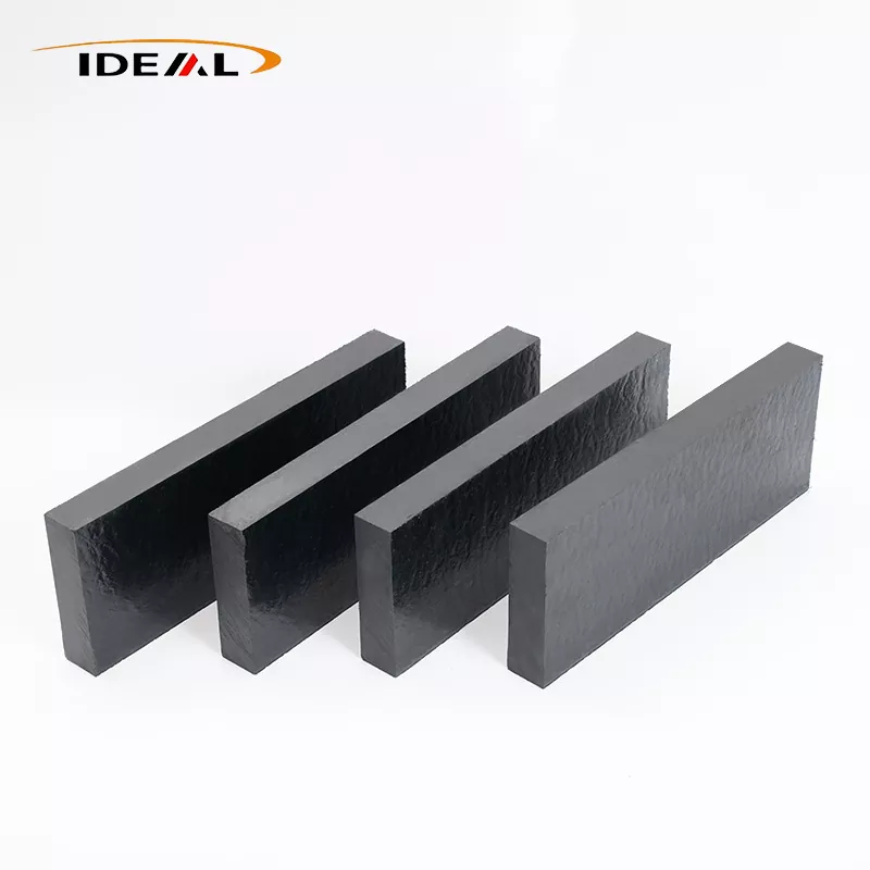
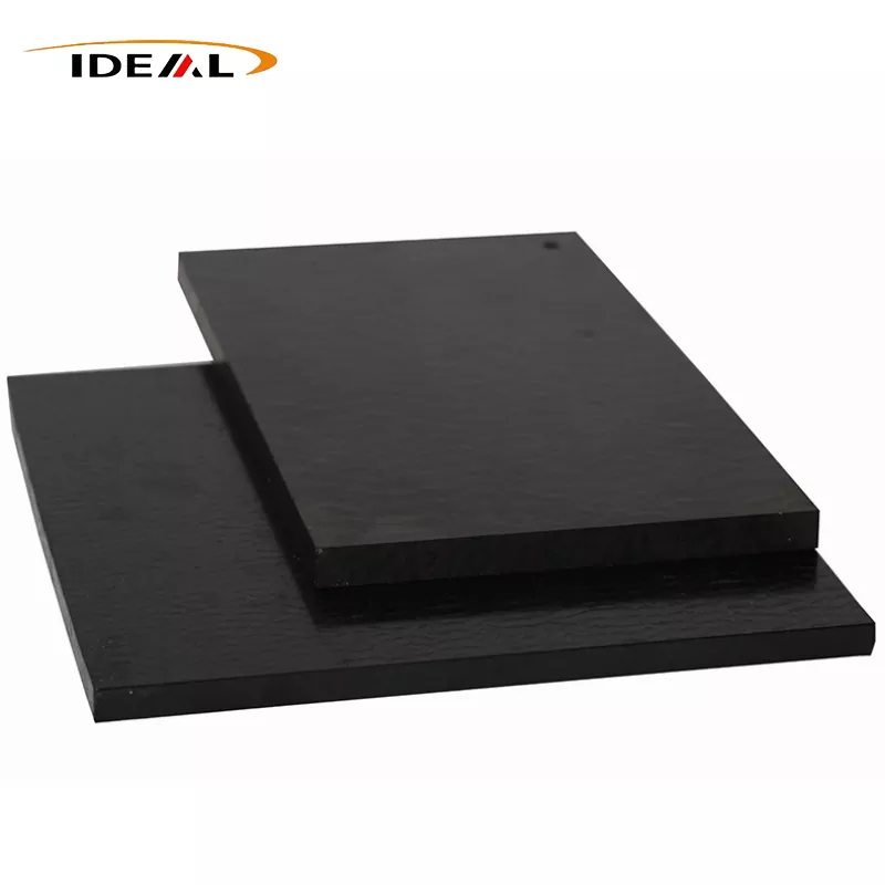
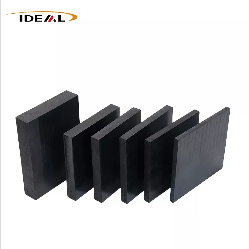
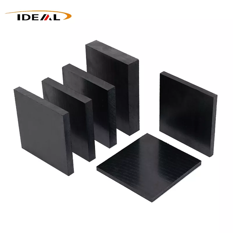
Carbon fiber filled PEEK sheets retain PEEK matrix core advantages of high temperature resistance, chemical resistance, hydrolysis resistance and low outgassing. Reinforced with short carbon fiber to improve rigidity, creep resistance, thermal conductivity and anti-static performance. Readily CNC machinable for replacing metals, glass fiber reinforced plastics and general engineering plastics.
Product Description:
1. Two Primary Manufacturing Processes for Carbon Fiber Filled PEEK Sheets
A. Extrusion Molding
Formulation: PEEK resin powder / pellets + short carbon fibers (3–12 mm, typical loading: 10–30 wt%) + minor high‑temperature processing aids.
Carbon fibers are pre‑sized to improve interfacial adhesion. The compound is dried to remove moisture and prevent voids and silver streaks.
The compounded pellets are fed into a high‑temperature single‑screw extruder, followed by calibration, cooling haul‑off, and cut‑to‑length shearing.
Post‑processing steps include annealing to tailor crystallinity and relieve internal stress, ultrasonic testing, dimensional inspection, and fine grinding / sanding.
This process is suitable for thin sheets ranging from 0.5–30 mm. It enables continuous production and high throughput.
Limitations: Fibers become strongly aligned along the extrusion direction, creating significant property differences between machine direction (MD) and transverse direction (TD) (anisotropy) and inconsistent shrinkage rates. Machined parts are prone to warpage.
Extreme precision over T‑die and three‑roll temperatures is mandatory; minor temperature deviations cause uneven thickness, wavy edges and surface pitting. Thin sheets are more susceptible to residual stress, and annealing parameters are highly sensitive. Improper annealing directly leads to cracking.
B. Compression Molding
PEEK powder/pellets are dry‑blended with short carbon fibers. The weighed mixture is loaded into a heated mold, evacuated under vacuum, heated until molten, and held under pressure to allow melt flow, compaction and degassing.
Cooling is controlled gradually to target 30–35% crystallinity and minimize warpage and internal stress. Pressure is released only after the stock cools below 200°C before demolding.
Ideal for thick sheets (6–100 mm) and large blanks. Random fiber orientation delivers far lower anisotropy than extruded sheets, making compression‑molded stock the preferred choice for precision CNC machining.
Limitations: A uniform cooling rate of 5–10°C/min must be maintained. Uneven cooling produces inconsistent crystallinity, residual stress and warpage. Thick stock (>20 mm) struggles with trapped porosity due to difficult outgassing. Vacuum‑assisted compression molding demands reliable mold sealing and synchronized pressure control. Large‑format sheets suffer from non‑uniform thermal fields, leading to mismatched crystallinity between edges and the core.
2. Performance Trade‑Offs Introduced by Carbon Fiber Loading
1. Anisotropy: While the sheet appears macroscopically homogeneous, tensile strength along the fiber orientation is substantially higher than in the transverse direction. Parts will fail prematurely if loaded along the weak axis — this is an inherent drawback of extruded PEEK sheet. Extrusion induces fiber alignment by default; process optimization can only reduce anisotropy, not eliminate it. Annealing relieves stress but does not erase fiber orientation.
2. Reduced Impact Toughness: Carbon fiber reinforcement boosts stiffness, wear resistance and thermal conductivity at the cost of markedly lower toughness compared to unfilled PEEK. Impact resistance and crack tolerance are degraded, so this grade is not recommended for components subjected to impact loads.
3. Limited Long‑Term Stability in Hot Aqueous Environments: Chemical resistance of the PEEK matrix remains intact. However, the fiber‑matrix interface acts as a weak boundary under prolonged cyclic exposure to hot water or steam. Moisture gradually penetrates this interface, causing progressive property degradation over time.
4. Direction‑Dependent CTE: Carbon fiber lowers the coefficient of thermal expansion, yet expansion rates differ across axes. Thermal cycling can alter clearances or interference fits in assemblies mated with metal components.
5. Sensitive Wear Behaviour: Carbon fiber Filled PEEK sheets deliver outstanding wear performance, but wear still occurs under starved lubrication, elevated temperatures or high PV conditions. Hard carbon fibers induce abrasive wear on mating metal counterfaces, scoring shafts and sealing surfaces.
3. Grade Classification by Carbon Fiber Weight Loading (wt%) — Guangzhou Ideal Carbon Fiber Filled PEEK Plates
CF10: 10% carbon fiber loading. Retains better toughness with only moderate stiffness improvement.
CF20: 20% carbon fiber, balanced grade (equivalent to PEEK 450CA20).
CF30: Industry standard workhorse grade with 30% carbon fiber (PEEK 450CA30). Balanced stiffness, wear resistance and thermal conductivity; widely adopted in semiconductor and general machinery applications.
CF40: 40% carbon fiber (PEEK 450CA40). Highest stiffness and thermal conductivity, paired with reduced toughness, heavier machining dust and greater machining difficulty.
Note: Higher carbon loading reduces volume resistivity and improves conductivity, while impact toughness continues to decline. CF40 offers higher modulus and better thermal conductivity but a higher friction coefficient and greater notch sensitivity. CF10 retains superior toughness and a slightly lower friction coefficient.
4. Residual Stress Testing, Acceptance Criteria & Suitable Non‑Destructive / Minor‑Destructive Inspection Methods for Carbon fiber Filled PEEK sheets
Slitting Method: Fine slots are machined into the sheet. Digital Image Correlation (DIC) captures springback deformation to map in‑plane stress distribution. Well suited for bidirectional MD/TD stress characterization on extruded sheets.
Ring‑Core Method: Measures through‑thickness stress gradients, preferred for thick compression‑molded plates.
FIB‑DIC (Microscale): Resolves localized stress concentration around carbon fibers.
Acceptance Limits
1. Precision compression‑molded blanks for semiconductor applications: residual stress< 8 MPa after annealing.
2. Standard extruded sheets: residual stress<12 MPa after annealing.
Important annealing guidance: Annealing temperature cannot be raised indefinitely. Temperatures far above the PEEK glass transition temperature (Tg = 143°C) reinitiate crystallization and introduce new residual stress.
Optimal annealing window: 150–165°C. Soak duration scales linearly with thickness (1 hour per 10 mm). Cool at ≤2°C/min. Rapid cooling renders the annealing cycle ineffective.
|
Product name |
Carbon fiber Filled PEEK sheets |
|
Material |
Carbon fiber filling PEEK |
|
Color |
black |
|
Breadth |
600mm-1250mm |
|
Thickness |
3mm - 100mm |
|
Thickness Tolerance |
Extruded sheets: ±0.1 mm (precision); ±0.2 mm (standard),Molded sheets: ±0.2~±0.5 mm, tolerance increases with thickness |
|
Flatness (Warp): |
Molded sheets: ≤0.5 mm/m (low stress precision grade),Extruded sheets: ≤1.0 mm/m |
|
Porosity |
Molded sheets ≤1% (high-end semiconductor), standard ≤2%; extruded sheets have lower porosity |
|
Volume resistivity |
10³–10⁶ Ω・cm (Semiconductive, large resistance fluctuation, cannot be directly used as ESD material) |
|
Tensile Strength |
≥250 MPa |
|
Tensile Modulus |
≥27 GPa |
|
Flexural Strength |
≥320 MPa |
|
Flexural Modulus |
≥23 GPa |
|
Simpeded Beam Impact |
Unnotched impact ≥6 kJ/m² |
|
sample |
Free |
1. Dimensional Stability
2. Flame Retardancy
3. Electrical Properties
4. Chemical Stability
5. Mechanical Performance
6. Wear Resistance
Application Scenarios
- IT Manufacturing
- Aerospace
- Medical
- Transportation
- Chemical Processing Equipment
Unsuitable Application Conditions
1. Not recommended for components subjected to high impact loads (reduced toughness)
2. Standard Carbon fiber Filled PEEK plates are not suitable for use as stable grounding conductive materials
3. Neat CF30 is not ideal for long-term dry sliding against soft metals (risk of scoring the mating counterface)
4. Extruded sheets carry inherent fiber orientation; avoid for multi-directionally loaded circular parts or ultra-precision zero-warpage components — compression-molded stock is preferred
Our Quality Assurance Specifications
1. Virgin Raw Material: 100% prime PEEK pellets; no regrind, reprocessed powder or foreign contaminants permitted.
2. Carbon Fiber Loading: Stated target ±2 wt% (e.g., CF30 = 28–32 wt%), verifiable via TGA thermogravimetric analysis.
3. Carbon Fiber Specification: Chopped carbon fiber sized for compatibility with PEEK; controlled fiber length retention without excessive attrition from over-shearing.
4. Contamination Control: No unintended inclusions; no misformulation with GF, graphite or PTFE.
5. Batch Consistency: Tight control of carbon content, crystallinity, resistivity and mechanical property variation within each production lot.
6. Visual Requirements: Uniform black colour, no obvious colour shift, yellowing or burn marks. Surface free of pinholes, voids, pits, pitting, scratches, indentations and clustered fiber bundles. Compression-molded sheets may have a uniform fine matte finish; extruded sheets can be supplied as mirror or precision-ground finish. No visible porosity, dark inclusions, knit lines or delamination. Carbon fiber agglomeration is prohibited. Clean cut edges free of chipping, burrs and burn marks.
7. Ultrasonic Testing: No continuous void planes, delamination or large internal pores. Premium batches require 100% UT inspection.
8. Metallographic Cross-Section: Homogeneous carbon fiber dispersion without agglomeration; sound fiber-matrix bonding with minimal interfacial debonding.
9. DSC Crystallinity: Target range 30–35%; within-batch crystallinity variation ≤ ±2%.
Our Technical Insight
Carbon fiber surfaces act as heterogeneous nucleation sites. During cooling, a transcrystalline layer forms around fibers. Its crystal orientation differs completely from the spherulitic structure of the bulk PEEK matrix. Typically several micrometres thick, this layer directly determines interfacial shear strength, hydrothermal ageing lifespan and fatigue behaviour.
1. Cooling rate dictates transcrystalline thickness: Rapid cooling yields a thin transcrystalline layer and weak interfacial bonding; excessively slow cooling creates an over-thick transcrystalline layer and concentrates internal stress.
2. Carbon fiber sizing is a decisive factor: Standard epoxy-sized carbon fiber cannot be used directly with PEEK. Even after compounding and pelletizing, the transcrystalline layer remains discontinuous, and interfacial debonding rate under hydrothermal cycling increases by 2–4 times. Continuous transcrystalline formation requires PEEK-specific thermoplastic sizing.
3. For identical CF30 loading, different sizing chemistries can produce greater than 30% disparity in short-beam shear strength (ILSS). TGA carbon content testing alone cannot detect this difference.
4. Failure sequence under hydrothermal ageing: Water molecules preferentially invade the boundaries of the transcrystalline layer rather than attacking the PEEK matrix first. This explains why many customers pass bulk immersion tests yet observe delamination and debris generation after repeated steam cycling of finished parts.
5. PEEK has extremely high melt viscosity. Carbon fibers fed into the main feed throat will undergo continuous shear and excessive shortening. Side feeding paired with synchronized loss-in-weight feeder timing locks in stable fiber length retention. Variation in retained fiber length causes batch-to-batch divergence in modulus, creep resistance and ILSS — invisible to TGA carbon content measurement.
We implement routine batch sampling for ILSS testing and metallographic transcrystalline examination.
FAQ
Q1: What is the most critical hidden quality risk for Carbon fiber Filled PEEK sheets?
A1: Uncontrolled crystallinity, residual internal stress, uneven fiber orientation, poor interfacial adhesion and subsurface porosity, which lead to post-machining warpage and premature component failure.
Q2: Why does Carbon fiber Filled PEEK tend to chip during machining?
A2: Chipping arises from weak fiber-matrix bonding combined with fiber orientation, causing fiber pull-out under cutting loads. Recommended practices: PCD cutting tools, low feed rates and climb milling.
Q3: Is warpage of Carbon fiber reinforced PEEK sheets always a quality defect?
A3: Not necessarily. Differential shrinkage induced by fiber orientation is an intrinsic property of extruded sheet. Warpage on compression-molded stock usually indicates improper processing: uneven cooling or incomplete stress relief.
Q4: What performance differences exist between compression-molded Carbon fiber Filled PEEK plates and extruded CF PEEK?
A4: Compression-molded sheets deliver isotropic mechanical behaviour and low residual stress. Extruded sheets achieve superior strength along the machine direction but weaker transverse properties and higher warpage tendency.
Q5: Why must carbon fiber be side-fed during compounding?
A5: Co-feeding through the main throat exposes fibers to aggressive screw shear, shortening fiber aspect ratio and substantially reducing stiffness and wear performance.
Q6: Do compression-molded PEEK CA30 sheets have zero stress?
A6: Compression-molded stock still contains residual stress, albeit far lower than extruded sheet. Precision parts still require annealing, with smaller springback magnitude.
Q7: Why can two batches of compression-molded PEEK CA30 plates show large modulus gaps even when TGA carbon content matches?
A7: As-received fiber length, sizing chemistry, transcrystalline continuity and through-thickness crystallinity gradients all exert major influence on modulus. Carbon loading is only one performance indicator.
Q9: Why do holes still chip after annealing?
A9: Two common causes: (1) Over-annealing raises crystallinity excessively and reduces toughness; (2) Surface crystallinity is lower than core crystallinity, creating mismatched mechanical properties across the section.